Technical Foundations is a series diving deeper into the technology underlying Holo’s PureForm metal additive manufacturing (AM) process and how it contributes to building high resolution, high accuracy metal parts at flexible production scales.
If you’ve spent any time in the world of plastics additive manufacturing (AM) within the last few years, you’ve probably run into the DLP — digital light processing — 3D printing process, but it’s been noticeably absent when the conversation shifts to metals (we’ll get into the reasons why in a little bit).
DLP technology underpins an optical processing technique originally developed for high definition digital projectors, that allows extremely precise, high-resolution images to be projected, via pixel-level control of the light transmitted from a source. This powers the projection of crisp, beautiful images at your local movie theater, but they can also selectively transmit light across an area of photopolymer (light-curable) resin in order to simultaneously cure an entire layer of a 3D print, and successively build up layers until a part is fully formed.
DLP-based 3D printing is fast, can produce extremely intricate and accurate micro-scale geometries, and leverages mass-produced, commercially-available electronics that yield relatively lower-cost 3D printing hardware. All of these characteristics are highly attractive and have made DLP-based 3D printing processes a growing force to be reckoned with in the polymer 3D printing space. DLP 3D printing for metals, however, is a much more challenging problem, one that Holo has spent the last half of a decade solving.
What is Holo PureFormTM technology?
Before we dive in too deep, let’s discuss why we’re talking about DLP 3D printing at all. Holo’s PureForm metal 3D printing technology leverages a two-stage process based on a unique combination of:
- DLP 3D printing of a metal-photopolymer slurry to produce ‘green bodies’
- Metal injection molding (MIM)-based sintering of those green bodies into solid metal parts
The DLP process is the foundation for the 3D printing component of Holo’s technology, and how we actually form the physical geometries of the parts we build for you, before they’re sintered. We’ll talk about the MIM side of things in a separate post — today we’re focusing on DLP-based 3D printing, how it works, and how we’ve adapted, improved, and optimized it to create end-use metal parts.
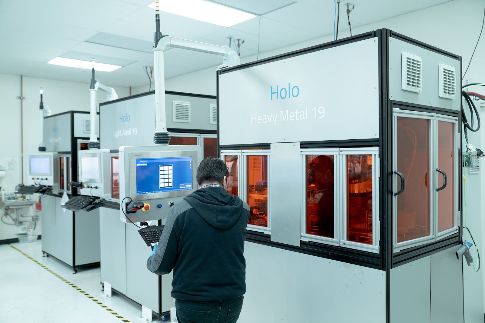
Holo’s 3D printers leverage DLP technology to drive our PureForm™ metal AM process. Pictured above are three units from the in-house Holo fleet.
Why does it matter?
Product development engineers (potentially like yourself!) building complex, custom assemblies often need to source intricate metal parts for their projects. Every application is different but typically, the most challenging parts have desired functional requirements around the following categories:
- Intricate function-driven geometries
- Tight dimensional accuracy and tolerances
- High-quality surface finish
- Consistent, predictable mechanical properties
- Rapid turnaround for fast design iterations
In an ideal R&D world, an engineer could produce any geometry they could dream up and design, enabling them to test even the most outlandish of ideas at least once. Back in real life, we’re limited both by the capabilities of the manufacturing processes available to us, as well as the economics of those processes. After all, even the most functionally capable technology isn’t very attractive to most R&D teams if it takes months and expensive tooling to produce a single design iteration. And small volume parts orders may be technically feasible, but not worth a CNC machine shop’s time to manufacture except at a price that may be too expensive for you.
This leaves an unfulfilled need for new tools with a greater capability to produce intricate, functional metal parts, more quickly and at lower cost, that can help accelerate the work of engineers designing complex assemblies.
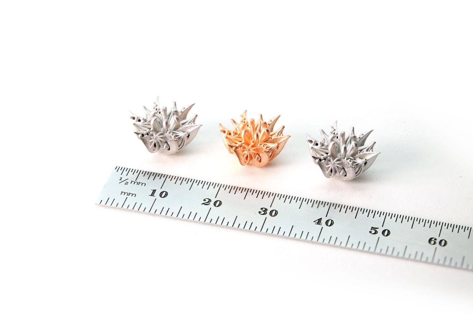
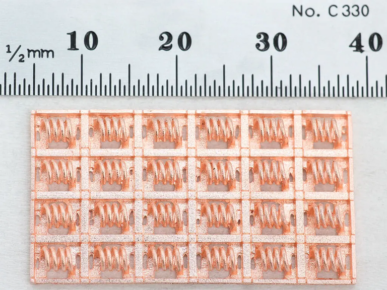
Intricate prototype geometries with organic surfaces created with Holo’s PureForm™ metal 3D printing technology. These parts can only be made using PureForm™, but similar parts could probably be replicated via a lost-wax casting process, requiring significantly more manual effort and process steps, which drive a higher cost and longer lead time. That might render these parts uneconomical and lead a designer to abandon this experiment.
Metal 3D printing via DLP technology becomes particularly interesting when viewed from this perspective. A DLP-based process is extremely accurate, high-resolution, and very fast. Paired with PureForm™ materials and downstream sintering, it’s fully capable of delivering on our customers’ exacting requirements around the performance of their metal parts. DLP 3D printing also requires no tooling or extensive manual machine setup, and can be extremely cost-effective for advanced applications in both low and medium volumes when compared with potential alternatives like Swiss CNC machining, investment casting, or laser powder bed fusion (L-PBF) 3D printing. When combined with MIM metal powders and sintering processes, and Holo’s proprietary materials and process control software, DLP 3D printing becomes a powerful technology to quickly and easily produce engineering-grade metal parts with tiny individual features.
The inner workings
To really understand why DLP 3D printing is so capable, we need to dive into the device at the heart of a DLP chipset, a type of micro-opto-electromechanical system (MOEMS) called a digital micromirror device (DMD).
DMDs were invented by Dr. Larry Hornbeck at Texas Instruments in 1987, and are composed of a microscopic rectangular array of individually controllable mirrors, each only a few microns wide, corresponding to the pixel resolution of the image the DMD controls. For example, a 1920x1080 resolution image can be controlled by 1920x1080, or approximately 2 million individual mirrors, all packed into a tiny microchip that fits easily in your palm.
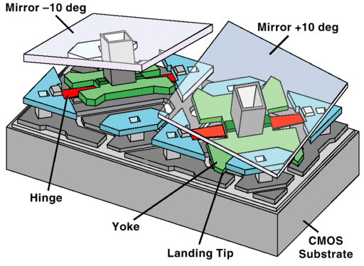
Diagram of two mirror units from a DMD, demonstrating the two different rotational positions to which each of the mirrors in the DMD can be individually commanded. Note the torsional hinge and yoke arrangement that drive the mechanics of how the mirrors are rotated. (Source: Projector Junkies)
Each individual mirror in the DMD can commanded to rotate to one of two operational positions over an angular path of roughly 20-24˚, and light hitting the DMD can either be reflected into a lens (for projection onto a target) or rejected onto a heatsink at each mirror position, thereby controlling whether each pixel is ‘on’ or ‘off’. DLP system mechanics can get more complicated when you introduce different colors (which isn’t necessary for 3D printing), as well as a technique called ‘pixel-shifting’ that can produce higher resolution output as a multiple of the physical mirror configuration. At a high level however, the function of a DMD is to precisely control the transmission of light through an optical system with pixel-level resolution.
The operation of a single mirror in the DMD array, demonstrating how the position of the mirror will either transmit a pixel’s worth of light to downstream focusing lenses, or reject it onto a heatsink to carry heat away from the system (Source: ProjectorScreen.com)
High-resolution control over a projected light source is what drives the accuracy of Holo’s PureForm 3D printing technology. If you’ve ever gone to a movie theater with a digital projector screen, you’ve seen how a DLP-based system can produce crisp, high-definition images without visual defects, even at dozens of feet away from the source. This ability to create perfectly sharp, high-resolution images with a high degree of accuracy creates a powerful tool when applied to a 3D printing process.
It’s science! Adding photopolymers to the mix
How do we take high-resolution images defined in light and turn them into a complex, highly accurate physical part? By projecting them onto a light-curable photopolymer and building up a part, one cured layer at a time!
Photopolymers are a class of thermoset polymer resins that are defined by irreversible physical changes in reaction to an applied light source. In the context of 3D printing, photopolymer feedstocks are liquid resins which harden into solid materials when exposed to a light source. That light source usually involves either tracing a point-source laser across a layer geometry, as used in traditional stereolithography (SLA) 3D printing, or curing the pattern of an entire layer of geometry simultaneously via a digital projector as in the DLP-based processes we’ve been exploring. Photopolymerization printing with LCD screens is also possible for certain use cases.
Without getting too much into the materials science behind photopolymerization (Wikipedia has a great primer if you want to learn more), photopolymers often contain a mixture of polymer-precursor compounds and photoinitiators, the latter of which react to light and catalyze, or kick off, a chemical reaction, creating cross-linking bonds between the various compounds in the photopolymer, and hardening or ‘curing’ it into a solid.
Photopolymerization can be fast too: with a light source that delivers sufficient intensity at a wavelength tuned for the specific photopolymer (often in the UV spectrum), curing can be completed in just a few seconds. This is where DLP-based 3D printing processes really shine — they typically deliver much higher light intensity than LCD-based ones, and cure an entire build layer at a time versus the slower, point-laser tracing operation of SLA 3D printing solutions.
So now we can precisely control light via a DLP chip, and use it to cure a photopolymer in a series of layers. That’s all well and good if you’re making polymer (plastic) parts, but where does the metal come into play? For that, we’ll need to discuss Holo’s unique PureForm™ materials.
DLP photopolymers + metal powder = Holo PureForm?
Traditional DLP-based printing involves curing photopolymers to produce plastic (polymer) parts. To produce 3D printed parts that can then be sintered into solid metal components (similar to what are known as ‘green bodies’ in the MIM industry), we need to add one more component to these liquid photopolymer feedstocks: metal powder. It’s not quite as simple as that of course: the challenge lies in designing a feedstock with enough metal powder to produce a solid metal component without defects after sintering, and ensuring that the powder is uniformly distributed throughout the photopolymer — all while retaining ability to print that feedstock in a DLP system.
We’ll cover Holo’s differentiated materials in more detail in a separate post, but at a glance, to develop our PureForm metal 3D printing technology on top of a DLP-based process, we needed to develop a feedstock with:
- Sufficiently concentrated metal powder loading to produce a sinterable part
- High enough photopolymer viscosity to maintain a well-distributed homogeneous mixture
- A clean burning (‘low ash’) photopolymer that will evacuate from parts during sintering without altering the metal material composition
Fundamentally, our 3D printing process uses a DLP projector to quickly cure thin layers of high viscosity metal powder-filled photopolymers into complex geometries, trapping the highly loaded, uniformly distributed metal powder throughout the part in the process. Since we’re using DLP technology, we can print quickly — we cure the entire patterned layer simultaneously and each layer only takes a few seconds to cure, regardless of how many parts are in a build. The resulting ‘green’ parts are then sintered in a separate MIM furnace to burn out the binder cleanly — without introducing impurities in material composition — and fuse the metal powder into a solid, highly accurate part.
The agility of digital manufacturing
It’s important to note that in all types of 3D printing, the geometry of a part is formed via the digital manipulation of the printing process, energy source, and/or printer mechanics, and not through a fixed geometry tool like a mold. This allows 3D printing processes, including the DLP-based technology we’ve developed here at Holo, to be extremely flexible and infinitely reconfigurable — you can print a build of various parts and immediately afterwards print a completely new set of geometries with no need to manufacture or change out fixed geometry tools.
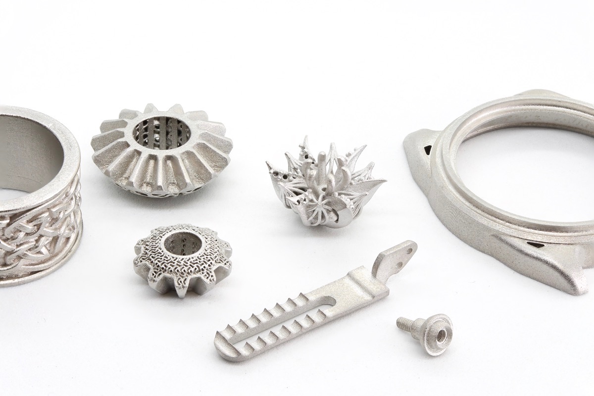
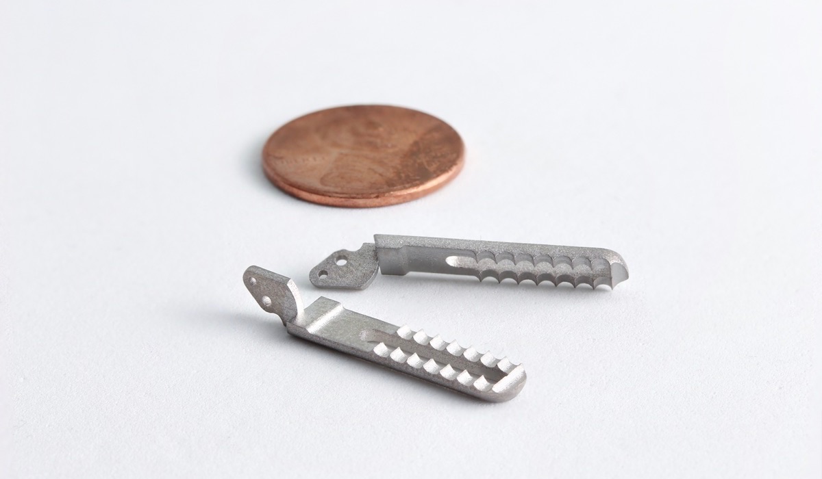
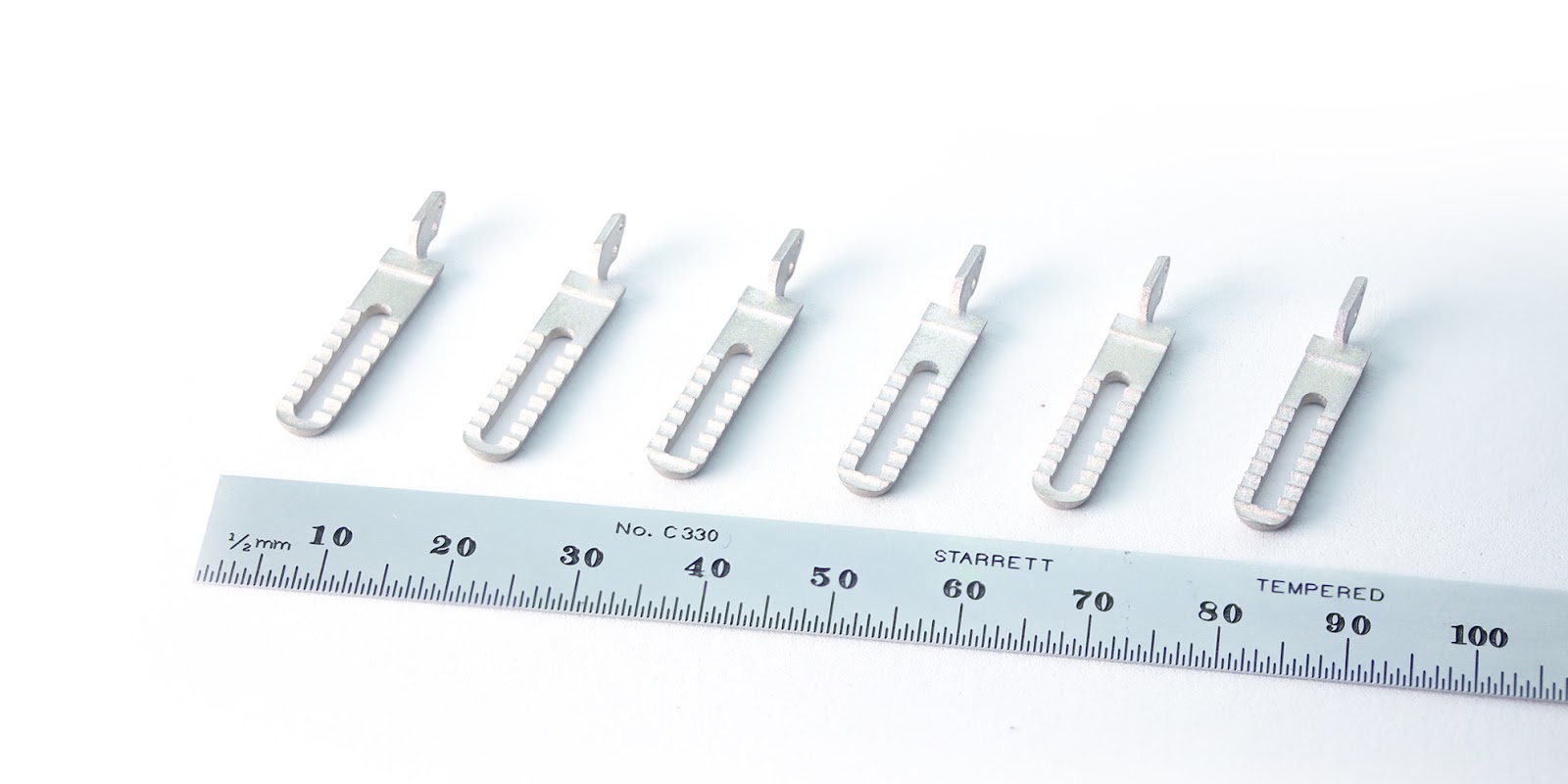
Digital manufacturing makes it easy to create new geometries on the fly without length setup or tooling costs. Pictured here, a range of different components produced by Holo’s PureForm metal 3D printing process.
Pairing our DLP 3D printing process with MIM sintering technology enables us to deliver highly agile production of high-resolution metal parts, and offer you a rapid pace of design iteration that’s simply not possible with traditional manufacturing technologies.
DLP technology makes it possible.
—
If you’d like to see how much faster you can drive product development with our PureForm metal 3D printing service, get in touch with our team to discuss your project!